You use the CC1101 when you want a low-power rf transceiver that works well for wireless projects. This sub-1 ghz transceiver can work in ism bands like 315, 433, 868, and 915 MHz. The cc1101 module gives good performance for low-power wireless uses. You can find the cc1101 in home automation, security systems, and sensor networks. The cc1101 module helps save energy and keeps wireless communication steady. You need to know each pin, read the CC1101 Datasheet, and learn how to set up the cc1101 for your low-power wireless projects.
Key Takeaways
-
The CC1101 is a wireless module that uses little power. It works in many frequency bands and helps save energy. This makes it good for projects that need to last a long time.
-
You need to know the right pinout and wiring to use the CC1101. This helps you connect it safely and stops damage or errors in communication.
-
You can use the CC1101 with microcontrollers like Arduino. You do this by using SPI and open-source libraries. This makes setup fast and easy.
-
The CC1101 is good for things like home automation, sensor networks, and security systems. These are places where you need strong wireless communication.
-
Fixing common problems like wiring mistakes, power supply, and frequency settings helps the wireless range and performance get better.
CC1101 Datasheet
Key Features
The cc1101 is great for wireless projects because it is flexible and works well. It can use both asynchronous and synchronous serial modes. This gives you more ways to connect and send data. The cc1101 datasheet says it has packet handling built in. This means your microcontroller does not need to do everything. Your project becomes easier and more reliable.
Here are some important features you should know:
-
High sensitivity lets you talk over long distances.
-
You can set the output power up to +12 dBm.
-
It supports many modulation formats like 2FSK, 4FSK, GFSK, MSK, OOK, and ASK.
-
It starts up fast, in just 240 microseconds.
-
Sleep mode uses very little power, as low as 200 nA.
-
It has advanced packet handling and data buffering.
-
The SPI interface makes it easy to connect to microcontrollers.
-
There is a built-in temperature sensor for better control.
-
The small 20-pin package is easy to put on a board.
The cc1101 datasheet also shows it meets FCC and CE rules. You can use it in many countries because it follows global standards. Some modules add RoHS or IP67 for extra safety.
Tip: Always look at the cc1101 datasheet for the newest features and updates before you start your project.
Frequency Bands
The cc1101 lets you pick from many frequency bands. You can use it in ISM bands that are free to use in many places. This helps you make wireless systems that work almost anywhere.
| Supported Frequency Bands | Typical Regional Use |
|---|---|
| 300-348 MHz | Custom/Industrial |
| 387-464 MHz | 433 MHz ISM (Europe/Asia) |
| 779-928 MHz | 868 MHz (Europe), 915 MHz (USA/Canada) |
You can set the cc1101 to work at 315, 433, 868, or 915 MHz. The cc1101 datasheet tells you how to pick the right frequency for your area. Always check the rules in your country before using wireless devices.
Power and Performance
You want your wireless project to last a long time on battery. The cc1101 helps by using little power and smart power modes. The cc1101 datasheet gives you all the numbers you need to plan your power use.
| Specification | Details |
|---|---|
| Voltage Supply Range | 1.8 V to 3.6 V |
| RX Current (typical) | 14.3 mA to 17.1 mA |
| TX Current (typical) | 12.3 mA to 34.2 mA (depends on output power) |
| Sleep Mode Current | As low as 200 nA |
| Output Power | Programmable up to +12 dBm |
| Max Data Rate | Up to 600 kbps |
| Operating Temperature | -40°C to 85°C |
| Startup Time | 240 µs (sleep to RX/TX) |
You can change the output power to get more range or save battery. Lower power means less range but longer battery life. Higher power gives more range but uses more current. The cc1101 datasheet helps you pick the best settings.
The cc1101 module is good for sensor networks, home automation, and remote control. It gives you steady and reliable wireless communication. If you need more range, you can use a range extender like the CC1190.
Note: Always get the official cc1101 datasheet from Texas Instruments. This gives you the best and newest info for pins, circuits, and fixing problems. Sometimes, module makers have their own cc1101 datasheets with extra details. But the TI datasheet is the main one you should use.
CC1101 Pinout
Pinout Diagram
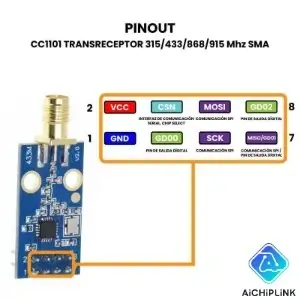
When you work with the cc1101 module, you need to know the exact pinout. The pinout tells you how to connect each pin to your microcontroller or circuit. The standard cc1101 uses a 20-pin VQFN package. Most module makers follow this layout, so you can use this table for your projects.
| Pin No | Pin Name | Description |
|---|---|---|
| 1 | SCLK | SPI clock input |
| 2 | SO (GDO1) | SPI data output / general digital output |
| 3 | GDO2 | General digital output for status or test signals |
| 4 | DVDD | Digital power supply (1.8 - 3.6 V) |
| 5 | DCOUPL | Digital power supply output for decoupling |
| 6 | GDO0 | General digital output / analog test I/O |
| 7 | CSn | SPI chip select input |
| 8 | XOSC_Q1 | Crystal oscillator pin 1 / external clock input |
| 9 | AVDD | Analog power supply (1.8 - 3.6 V) |
| 10 | XOSC_Q2 | Crystal oscillator pin 2 |
| 11 | AVDD | Analog power supply |
| 12 | RF_P | Positive RF input/output |
| 13 | RF_N | Negative RF input/output |
| 14 | AVDD | Analog power supply |
| 15 | AVDD | Analog power supply |
| 16 | GND | Analog ground |
| 17 | RBIAS | External bias resistor input |
| 18 | DGUARD | Digital noise isolation power supply |
| 19 | GND | Digital noise isolation ground |
| 20 | SI | SPI data input |
📌 Tip: Always check the datasheet for your specific cc1101 module. Some modules may have small changes in pin configuration, but most follow this standard layout.
Pin Functions
You need to understand the pin configuration and descriptions to connect the cc1101 correctly. Each pin has a special job. Here is what each pin does:
-
Power Supply Pins:
-
DVDD, AVDD: These pins give power to the digital and analog parts of the chip. You must connect them to a stable voltage between 1.8 V and 3.6 V.
-
DCOUPL: This pin helps filter noise from the power supply. You connect a capacitor here for better performance.
-
GND: These pins connect to ground. They keep the module safe and stable.
-
DGUARD: This pin helps block digital noise from reaching sensitive parts of the chip.
-
-
SPI Interface Pins:
-
SCLK: This pin takes the clock signal from your microcontroller.
-
SI: This pin receives data from your microcontroller (MOSI).
-
SO (GDO1): This pin sends data back to your microcontroller (MISO).
-
CSn: This pin lets the cc1101 know when you want to talk to it. You set it low to start communication.
-
-
GDO Pins:
- GDO0, GDO1 (SO), GDO2: These pins can show status signals or send interrupts to your microcontroller. You can set them up for different uses, like showing when data is ready or when the module is busy.
-
RF Pins:
- RF_P, RF_N: These pins connect to your antenna. They send and receive radio signals.
-
Oscillator Pins:
- XOSC_Q1, XOSC_Q2: These pins connect to a crystal. The crystal helps the cc1101 keep time and stay on the right frequency.
-
Other Pins:
- RBIAS: You connect a resistor here. It helps set the right bias for the chip.
You must follow the correct pin configuration for your project. If you mix up the pins, the cc1101 will not work. Wrong connections can cause the module to fail or even break.
⚠️ Note: Many problems with the cc1101 come from bad wiring or wrong pin definitions. Always double-check your pinout and make sure you use the right voltage. If you use a 5V board, you may need a level shifter because the cc1101 only works with 1.8V to 3.6V. Good soldering and solid jumper wires help prevent bad contacts.
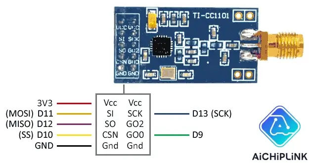
If you use an Arduino, connect the SPI pins to the right Arduino pins. For example, on most Arduino boards, use pins 10 (CSn), 11 (SI), 12 (SO), and 13 (SCLK). Use one of the GDO pins for interrupts if needed. Always match the pin configuration to your microcontroller and check the datasheet for details.
Correct pin connections make your wireless project reliable. You avoid communication errors and keep your cc1101 module safe. Careful attention to the pinout and pin configuration and descriptions will help you build a strong and stable wireless system.
CC1101 Circuit
Basic Wiring
You need a good circuit to get the best results from your cc1101. Start by making sure you have a clean power supply. Use a 3.3V regulator if your board runs on 5V. Place a 0.1µF capacitor close to the VCC and GND pins to filter noise. Connect the RF_P and RF_N pins to a simple wire antenna or a matched antenna circuit for better range. Add a 10kΩ resistor to the RBIAS pin and connect it to ground. This setup helps the cc1101 work well in your project.
💡 Tip: Keep your antenna traces short and straight. This reduces signal loss and improves wireless performance.
Arduino Integration
You can connect the cc1101 to an Arduino or similar microcontroller with just a few wires. Here is a simple wiring table for Arduino UNO:
| CC1101 Pin | Arduino UNO Pin |
|---|---|
| GND | GND |
| VCC | 3.3V |
| CSN | D10 |
| SCLK | D13 |
| MOSI | D11 |
| MISO | D12 |
| GDO0 | D2 |
| GDO2 | D3 |
⚠️ Note: The cc1101 needs 3.3V power and logic. If you use a 5V Arduino, add a level shifter to protect the module.
Follow these steps for connecting the cc1101 to an Arduino Pro Micro (3.3V):
-
Connect GDO2 to digital pin 9.
-
Connect CSN to digital pin 10.
-
Connect MOSI to digital pin 16.
-
Connect MISO to digital pin 14.
-
Connect SCLK to digital pin 15.
-
Connect VCC to 3.3V.
-
Connect GND to ground.
For quick integration into a circuit, you can use open-source libraries. The Elechouse CC1101 library makes setup easy. The RadioLib library also supports the cc1101 and gives you many example projects. These tools help you test your circuit and start sending data fast.
CC1101 Equivalent
Alternative Modules
You have several choices if you want an alternative to the cc1101 for your wireless project. The most common options include the CC1120, CC1125, and CC1200 from Texas Instruments. These chips work well in sub-1 GHz bands and offer similar performance, especially at 433 MHz with 2FSK modulation. You may also see modules like the NRF24L01, SI4463, and RFM69HCW. These alternatives support different frequency bands and features. For example, the NRF24L01 works at 2.4 GHz, while the SI4463 and RFM69HCW cover sub-1 GHz bands.
📝 Note: At low data rates and standard settings, the CC1120, CC1125, and CC1200 show only small differences in performance. You can expect similar blocking and selectivity, so your choice may depend on price or extra features.
Comparison
You should compare the main features before picking a module for your project. The table below shows how the cc1101 stacks up against popular alternatives:
| Feature | CC1101 | NRF24L01 | SI4463 | RFM69HCW |
|---|---|---|---|---|
| Frequency Bands | 300-928 MHz (sub-1 GHz) | 2.4 GHz | 315-915 MHz | 315-915 MHz |
| Max Output Power | Up to +12 dBm | +0 dBm | Up to +20 dBm | Up to +20 dBm |
| Sensitivity | -116 dBm | -85 dBm | -126 dBm | -120 dBm |
| RX Current | 14.3–17.1 mA | 12.3 mA | ~10 mA | 16 mA |
| TX Current | 12.3–34.2 mA | 11.3 mA | 85 mA (max) | 45 mA (max) |
| Sleep Mode Current | 200 nA | 900 nA | 50 nA | 100 nA |
| Max Data Rate | Up to 800 kbps | 2 Mbps | 1 Mbps | 300 kbps |
| Range | Moderate, extendable | Short | Long | Long |
| Cost | Low | Low | Medium | Medium |
| Application Areas | IoT, automation, security | IoT, toys | Industrial, IoT | IoT, sensors |
You get a good balance of range, power use, and cost with the cc1101. If you need longer range or higher output power, the SI4463 or RFM69HCW may work better. The NRF24L01 gives you higher data rates but only works at 2.4 GHz and has a shorter range. The CC1120 family is best if you want advanced features or need to match strict industrial standards.
💡 Tip: Choose your module based on your project's needs. If you want low power and low cost, stick with the cc1101. For longer range, try the SI4463 or RFM69HCW. For higher data rates, the NRF24L01 is a good pick.
CC1101 Applications
The cc1101 helps you make smart wireless systems that save energy. You can use it for sensor networks and home automation. It also works in many real-world projects. Here are some common ways people use it.
Wireless Sensor Networks
The cc1101 is used a lot in wireless sensor networks. These networks need to use little power and last a long time. The cc1101 is good for this because it does not use much energy. It also has a strong signal. You can use it for things like checking the environment, smart farms, or health tracking. The table below shows how well the cc1101 works in different sensor network jobs:
| Application Area | Description | Performance Metrics Achieved |
|---|---|---|
| Wireless Sensor Networks (WSNs) | Energy-saving communication using cc1101 as main data radio and wake-up radio | - Wake-up current as low as 2.7 μA- Wake-up range up to 41 m at +10 dBm- Over 100 m range with amplifiers- Packet delivery ratio near 100%- Node lifetime over two years |
| Environmental Monitoring | Single-hop and multi-hop WSNs where saving energy is important | - Long node lifetime- Reliable wake-up function |
| Body Area Networks (WBAN) | Short-range, low-power, reliable wake-up | - Wake-up range around 6 m at −10 dBm, good for body-worn sensors |
📝 You can make sensor nodes that last for years. They only send data when needed. This makes your wireless projects work better and cost less.
Home Automation
The cc1101 lets you control lights, alarms, and smart plugs at home. Many home systems use the cc1101 to send commands wirelessly. You get quick responses and save energy. You can also set up alarms that warn you if something changes. The cc1101 works in small homes and big houses.
-
Control lights and devices from anywhere in your house.
-
Use wireless door sensors and alarms.
-
Check temperature and humidity with wireless sensors.
Example Projects
Many cool projects use the cc1101. For example, the RadioShield project added a cc1101 to make a radio board. This board can do many types of wireless jobs. Researchers tested the cc1101 in data systems. They saw it uses very little power when sleeping. It also sends sensor data well. These projects show you can trust the cc1101 for low-power wireless work.
💡 Try making your own wireless sensor or remote control. The cc1101 gives you what you need to build your ideas.
Troubleshooting
Common Issues
Sometimes, wireless modules do not work as you hope. You might see problems that make your project stop working right. The table below shows problems people often have with these modules. You can look at this table to see if you have the same issues.
| Issue | Description |
|---|---|
| Very short communication range | You may only get 30-50 meters, much less than the expected 300 meters, even with a good antenna. |
| Low sensitivity | The module does not receive packets below about -85 dBm, while it should work below -100 dBm. |
| Constant LQI values | The link quality indicator (LQI) stays around 47-50, even if the signal gets weaker. |
| Output power increase ineffective | Raising output power from 0 to +10 dBm does not improve range and can even make it worse. |
| Crystal frequency mismatch | Using a 27 MHz crystal with software set for 26 MHz causes frequency errors and poor range. |
| Carrier Sense threshold tuning limited | Changing the CS threshold only helps range a little, not enough for most needs. |
| Firmware and configuration issues | Different settings or firmware can change range, but problems often remain. |
| Hardware variations | Both generic and official modules show similar range problems, so hardware alone is not the cause. |
🛠️ If your wireless signal is weak or your devices cannot talk far, check these problems first.
Solutions
You can fix many problems by following easy steps. Try these ideas to make your wireless range and signal better:
-
Use logic level converters if your microcontroller uses 5V. This keeps the SPI pins safe.
-
Check your GDO pin connections. These pins must match your software.
-
Run the calibration process to keep your module working well.
-
Make sure both boards use the same crystal frequency. If not, your range will be short.
-
Test your setup with low transmit power. See if the RSSI drops below -30 dBm. This helps you find link problems.
-
Try continuous RX mode and change the TX frequency. Find the highest RSSI to line up your boards.
-
Update your firmware and use the right register settings for your project.
-
Some features, like fixed packet length, only work on some boards.
🔍 Careful setup and testing help you get the best range with your cc1101 project.
You now know the basics about the CC1101. This module uses little power and is easy to connect with SPI. It can use different ways to send signals. Look at the table below for a quick review:
| Aspect | Details |
|---|---|
| Features | Low-power RF, many ways to send signals, up to +12 dBm output, works with many frequencies |
| Integration | Simple SPI wires, careful pin setup, clean power, good antenna and circuit design |
| Applications | Remote controls, smart homes, sensor networks, security systems |
Check out the official datasheets, Cirkit Designer, and GitHub libraries to learn more. Knowing about pin setup, circuit design, and other choices helps you make strong wireless projects.
FAQ
What is the maximum range of the CC1101 module?
You can get up to 300 meters in open space with a good antenna. Walls and obstacles will reduce the range. Try different antennas to see what works best for your project.
Can you use the CC1101 with Arduino?
Yes, you can connect the CC1101 to Arduino using the SPI pins. Use a 3.3V Arduino or add a level shifter. Libraries like RadioLib or Elechouse CC1101 make coding easier.
What antenna should you use with the CC1101?
You can use a simple wire antenna, a PCB trace antenna, or a ready-made 433 MHz whip antenna. The antenna type affects range and signal quality. Match the antenna to your chosen frequency band.
Why does your CC1101 not communicate?
Check your wiring and power supply first. Make sure you use the correct SPI pins. Double-check your frequency settings and crystal value. Use the same settings on both modules for a stable link.
Is the CC1101 legal to use in every country?
No, you must check your local wireless rules. Some countries limit which frequencies you can use. Always follow your country’s laws for wireless devices.

Written by Jack Elliott from AIChipLink.
AIChipLink, one of the fastest-growing global independent electronic components distributors in the world, offers millions of products from thousands of manufacturers, and many of our in-stock parts is available to ship same day.
We mainly source and distribute integrated circuit (IC) products of brands such as Broadcom, Microchip, Texas Instruments, Infineon, NXP, Analog Devices, Qualcomm, Intel, etc., which are widely used in communication & network, telecom, industrial control, new energy and automotive electronics.
Empowered by AI, Linked to the Future. Get started on AIChipLink.com and submit your RFQ online today!